The previous User Guide section on optical propagators gave background information on the propagation formulas used in LightLike. In the present section we complete that discussion by giving guidelines for specifying the discrete propagation mesh parameters that must actually be entered in LightLike model setup. Most prominently, these are the spacing of the mesh and the span (or dimension) of the mesh.
The size and spacing of the propagation mesh must be chosen very carefully; the spacing must be neither too large nor too small, and the mesh size must be large enough to capture the effects of interest, but making it too large can slow the simulation drastically. To a first approximation the execution time of most LightLike models varies roughly as the square of the propagation mesh dimension, so using 512x512 meshes takes roughly four times as long as using 256x 256 meshes.
To choose the mesh size and spacing correctly, there are a number of factors that must be taken into account, including
•the wavelength(s) of interest,
•the propagation distance,
•the horizontal extent of the regions of interest at both ends of the propagation path,
•whether a planar or spherical reference wave is used,
•the turbulence strength and its distribution along the path,
•the use of spatial filters and/or absorbing boundaries,
•the physical dimensions and configuration, in "output space", of the sensors used,
•the FFT (fast Fourier Transform) package used.
**********
UPDATE: An updated, revised and generalized discussion of the mesh selection guidelines that appear below is available in part 2 of the choosing mesh settings for optical propagation. Also, the guidelines in that document have been incorporated in the auxiliary PropConfig tool that is part of the LightLike release. Users who run the PropConfig tool as part of LightLike model building will find a PropConfig tab where suggested mesh specifications are computed, based on the user-supplied propagation scenario and the analysis in the just-referenced document.
**********
There are two main requirements: First, the mesh spacing must be small enough to adequately sample the variations in phase of both the wavefront and the quadratic phase factors applied by the Fourier optics propagator. To be specific, the phase difference between adjacent mesh points should never exceed half the wavelength. Second, the mesh extent must be large enough to capture all the propagated light, otherwise, as a consequence of the periodicity of Fourier transform, the light leaving one side of the mesh will reappear on the other side of the mesh; this effect is known as "wraparound". The two requirements are interrelated, because(1) the mesh spacing governs the maximum spatial frequency (and hence the maximum propagation angle) which can be represented on the mesh, (2) the sampling requirement for the quadratic phase factor increases linearly with the size of the region of interest, and (3) the mesh extent at each end should generally be at least twice as big as the region of interest at that end. The propagation distance and the choice of reference wave both affect the magnitude of the quadratic phase factors, and with a spherical reference wave the mesh extent and mesh spacing vary linearly along the path. Turbulence introduces additional phase perturbations - see How turbulence is modeled - and these enter into the phase sampling requirement. In some cases it is possible to mitigate wraparound effects, and thereby relax the requirement on mesh extent to some degree using spatial filters and/or absorbing boundaries - see How to use spatial filters and absorbing boundaries. The physical dimensions and configuration of the sensors used can generally be ignored, because LightLike will automatically interpolate the mesh at the entrance pupil as needed; however if you wish to avoid interpolation error you can choose the mesh spacing and offset accordingly. The FFT package governs what mesh dimensions are permitted, and LightLike can be used with several different FFT packages; some allow only powers of two, while others allow any integer which factors into powers of small primes, e.g. 2, 3, 5, and with at least on factor of two. For the Windows implementation of LightLike the FFT package used for optical propagation (provided by Intel) requires that the mesh dimension be a factor of two. A separate FFT package, more general but less efficient, is used for generating phase screens, but that those dimensions are set automatically anyway. Whatever the mesh dimension is, for a mesh of dimensioned n x n, by default the (n/2+1, n/2+1) point is assumed to fall on the optical axis.
We've spoken of the "regions of interest" at either end of the propagation path without precisely defining what we meant. For an optical system, the effective region of interest is closely related to the system aperture, but generally somewhat larger, to account for scattering effects. For example, when modeling the light incident on the aperture from a point source, we cannot model all of the light emitted by the point source, given the finite size of our meshes, so instead we model only that portion of the light which contributed to the wavefront received at the aperture. But with turbulence light will be scattered both into and out of the aperture; and with a true point source equal amounts would be scattered in and out on average. To match this in simulation we must consider a region containing the system aperture, and with enough of a margin on all sides that the light scattered out at the edges will not affect the average intensity across the aperture. For more details see modeling point sources. Similar considerations apply when modeling the light from an extended incoherent source, or a coherent reflection off an optically rough surface. At the other end of the path it is much the same, except that the physical extent of the object being imaged and/or illuminated plays the same role as the system aperture.
Consider the simplest case, where (1) we would use a planar reference wave, (2) the quadratic phase factors applied by the propagator dominate the phase sampling requirement, and (3) neither spatial filters nor absorbing boundaries are used. In this case the mesh requirements can be computed easily. Let λ be the wavelength, z be the propagation distance, D the maximum extent of the regions of interest at the two ends, nx the mesh dimension, and dx the mesh spacing. For a given λ and dx, the minimum and maximum propagation angle are -λ/dx and λ/dx, implying that light from any point on the mesh could expand to fill a region of size λz/dx after propagating a distance z. To avoid wraparound, the mesh extent should be at least twice that:
nx*dx >= 2λz/dx
This can be put in the form of an inequality for dx in terms of nx, or vice versa:
dx >= sqrt(2λz / nx)
nx >= 2λz / dx2
If D corresponds to the diameter of the aperture of an imaging system, λ/D is the classical resolution limit for the system. Generally, dx should be no larger than λz/D, the projection of that angle over the propagation distance. Putting that value in for dx in the inequality for nx gives us the minimum permissible nx, given our assumptions.
nxmin = 2λz / (λz / D)2 = 2D2 / (λz)
For example, if λ=10-6m, z=50km, and D=1.0m,
nxmin = 2*1.0*1.0 / (10-6*50,000) = 40
However, in order to use that nx, we must use the maximum value allowed for dx:
dxmax = λz/D = (10-6*50,000)/1.0 = 0.05m = 5cm.
Also, with those choices for nx and dx the mesh extent is just twice the aperture diameter. For many cases of interest that will not be acceptable, because a denser mesh will be required to properly sample turbulence effects, and because we must consider a region of interest larger than the aperture, as discussed previously. To decrease dx, we must increase nx, and it goes as the inverse square, so to halve dx, to 2.5cm in this case, we must quadruple nx, to 160. That would double the mesh extent, from 2.0m (40*5cm) to 4.0m (160*2.5cm), allowing us to enlarge the region of interest. For most cases involving propagation through turbulence, if we choose a mesh spacing sufficient to adequately to sample the turbulence effects, then choose nx to satisfy nx >= 2λz / dx2; that will give us more than enough room for the region of interest. Bear in mind that nx must be a valid dimension for the FFT package being used.
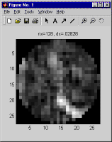
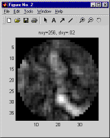
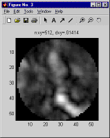
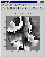
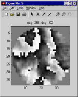
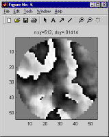
So the question arises, how should one pick dx, given the range, wavelength, and turbulence distribution? There is no hard and fast answer, because it depends on the degree of accuracy required, but as a general rule the maximum permissible dx will vary in proportion to the coherence length, which characterizes the spatial variation of the phase of a wavefront which has been propagated across the path of interest. For a planar reference wave we recommend that dx should be no greater than one fourth the minimum of the two plane wave coherence lengths, one computed in each direction. For a spherical reference wave we recommend that the dx at each end should be no greater than one fourth the plane wave coherence length computed in the corresponding direction. But for maximum surety, when modeling a propagation scenario different from those you've modeled previously, it is always a good idea to double-check that the dx you have picked is small enough. To do this, pick a few of the more stressing cases you plan to model, and run simulations both using the dx you hope will work, and also using a smaller dx, with a correspondingly larger nx. Compare the results - whatever results are relevant to your application - and use the differences between the corresponding runs to estimate the margin of error. As an example, below are shown the aperture plane intensity and phase obtained using three different choices of nx and dx for the same propagation scenario.
Incidentally, these results were generated using LightLikeStaticDemo, the system model created in the course of our step-by-step tutorial. The case we used approximates typical conditions at the Airborne Laser Advanced Concepts Testbed (ABL ACT) atop North Oscura Peak, on the White Sands Missile Range, in New Mexico.
When using a spherical reference wave the requirements pertaining to mesh extent and mesh spacing are much the same, but you now have an additional degree of freedom, the placement of the point to which the reference wave is converging to or diverging from, and that can sometimes be useful, especially when the region of interest is much larger at on end of the propagation path than it this at the other. But the sampling requirements must still be satisfied, and the mesh spacing increases in direct proportion to the mesh extent, so that will often be the limiting factor. Also, it is important to remember that since the reference wave is now curved, the phase difference between the reference wave and a wavefront with similar curvature is reduced, which tends to ease the sampling requirements, but the phase difference is increased for wavefronts that are basically flat or of the opposite curvature. It can be shown that the reference wave which minimizes the mesh dimension required to adequately sample spherical waves propagating in both directions is precisely that which projects the region of interest at one end to that at the other. Unfortunately there is no similarly simple criteria to ensure that turbulence effects are adequately sampled, but, as with planar reference waves, you can make an educated guess, based on the coherence length in each direction, then double-check.
LightLike supports rectangular propagation meshes - ny need not be equal to nx. Both, however, must satisfy all sampling requirements, but the requirements for the two axes may differ, because the extent of one or both regions of interest may be greater in one direction than in the other. At this time the spacing in both directions must be the same (i.e., dx = dy). Rectangular meshes may be used with either planar or spherical reference waves, the latter subject to the above caveat. It would be straightforward to add support for differing spacings in the two directions, and we could also add support for reference waves with different curvatures in x and y, both of which may be useful in modeling imaging and/or illumination of objects much longer in one direction than the other. If you think those capabilities might be important for your application, please contact us.
Once you have determined the mesh dimensions and spacing you wish to use, you need to put that information into your system model. This can be done using either of two components AtmoPath (the component usually used to model propagation through turbulence), or PropagationController, which gives you more detailed control. AtmoPath actually contains two PropagationControllers, inside it, one for each propagation direction, but most of their parameters have been hardwired, to make AtmoPath simpler to use. The reference wave is planar, the propagation mesh is square, and no spatial filtering or absorbing boundaries are used. The default modeling approaches for both point sources and speckle are used, both of which make use of the parameters superApDiameter and edgeSigma, which the user can specify. For details, see How point sources are modeledand How speckle is modeled. When AtmoPath is used, all propagations in both directions are modeled using all the same modeling parameters. Because of these simplifications, only four optical modeling parameters remain to be set:
propnxy the mesh dimension (same in x and y)
propdxy the mesh spacing (same in x and y)
superApDiameter used in modeling point sources and/or speckle
edgeSigma used in modeling point sources and/or speckle
Note: the other parameters of AtmoPath relate to modeling atmospheric turbulence, and their use is described in How turbulence is modeled.
