When modeling optical systems it is often necessary to model point sources. A point source can provide a direct measurement of a system's point spread function (PSF) and optical transfer function (OTF). For adaptive optics systems, a point source beacon maximizes the Strehl ratio. Off-axis point sources can be used to measure the effects of anisoplanatism. A single point source can be used to construct the image of a compact (i.e. smaller than an isoplanatic patch) incoherent source; multiple point sources can be used to construct the image of an extended incoherent source. Because of these special properties, point sources (actually "effective" point sources, such as a laser coming out the end of an optical fiber) are often used for calibration and experiments.
From the standpoint of theory - geometric optics or Rytov theory - point sources are easy to handle; for wave optics simulation this is not the case. In wave optics simulation a wavefront is modeled by a two-dimensional mesh of complex numbers. The mesh necessarily has both finite resolution, typically on the order of centimeters, and finite extent, typically on the order of meters. An ideal point source is infinitely compact, and radiates light uniformly in all directions; the outgoing wavefronts are complete spheres. Close to the source, the wavefront curvature goes to infinity. Far from the source, the wavefronts become far too large to represent on a practical mesh. This means that the direct approach - directly mapping the theoretical model to a numerical model - does not work.
The standard solution to this problem relies upon the fact that we are typically interested in only a small portion of the light from the source, the part that enters the aperture of the system of interest. One has to balance the desired characteristics for the field at the source plane with those at the aperture plane, taking into account the requirements of numerical propagation. At the source plane we simply want the field to be as compact - as pointlike -as possible. At the aperture plane, we want the field to have uniform amplitude over the aperture with a spherical phasefront centered on the source, because that is what we would expect for a true point source. When turbulence is present the instantaneous fields will be scintillated, but the time-averaged amplitude should still be uniform across the aperture. The time-averaged phase is ill defined, but the time-averaged phase gradient should correspond to a pure focus.
These requirements can be satisfied by constructing a field mesh at the aperture plane which has uniform amplitude, and the right phase curvature, over a region somewhat larger than the aperture, then doing a vacuum propagation back to the source plane. This is one of two methods supported by LightLike, and is the default. The second method emulates a technique that is often used by other analysts. This second technique is to start with a field at the source plane that has just a single nonzero mesh point, then apply a spatial filter which is unity over the angular region somewhat larger than the subtense of the aperture. This is essentially equivalent to the first method, except in the case where the nonzero region of the spatial filter chosen exceeds the subtense of the field mesh at the aperture. Ordinarily this would lead to problems due to wraparound, but these problems can be avoided by the judicious use of absorbing boundaries and spatial filters.
In the back-propagation method, the reason for making the uniform amplitude region larger than the aperture is to allow for scattering due to turbulence, as represented by the phase screens. For a true point source, the average amplitude is the same everywhere on a wavefront, and for any given point energy is as likely to be scattered in as scattered out. For our pseudo point source, points just inside the uniform amplitude region are more likely to lose energy then to gain it; this reduces the time-averaged amplitude for these points. By making the uniform amplitude region larger than the system aperture we can reduce or eliminate this effect for points inside the aperture. How much larger? That depends on the turbulence strength, the wavelength, the propagation geometry, and our error tolerance. As far as we know, no one has yet done a systematic study to look at this, although it would be straightforward.
If the uniform amplitude region at the aperture plane has a sharp edge, there will be significant energy at high spatial frequencies, which means that the field at the source plane will be less compact than we might like. If the uniform amplitude region is circular, the intensity at the source plane will be an Airy pattern, with its characteristic rings. By "softening" the edge of the uniform amplitude region, e.g. with a gaussian or cosine roll-off, we can reduce the high frequency content, resulting in a more compact field at the source plane. Unfortunately, this is not without cost. The roll-off region increases the size of the region of nonzero field, which is one of the factors that governs the minimum size of the mesh we can use, and simulation execution time increases roughly as the square of the mesh size.
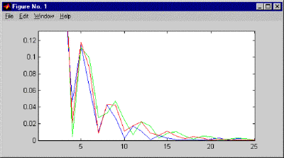
We did a series of experiments in Matlab to compare the effects of different roll-offs. We used three different shapes: a gaussian truncated at two standard deviations, a gaussian truncated at three standard deviations, and a half cosine wave. We used a 256x256 mesh; with a circular region of unit amplitude 64 mesh points across, and varied the width of the roll-off region from 1 to 32 meshpoints. Of the three shapes, we found that the two sigma gaussian was generally superior, in the sense that for a wide range of tolerances and roll-off widths, the maximum radius exceeding the tolerance was smallest for that shape. As an example, the figure below shows the field amplitude as a function of distance from the origin in mesh points for the three roll-off shapes. The amplitude for the two sigma gaussian is shown in blue, the three sigma gaussian is green, and the half cosine is red. For larger tolerances, greater than about .1 times the on-axis value in amplitude, or .01 in intensity, no roll-off helped. For very small tolerances, less than about .004 in amplitude, .000016 in intensity, the two sigma gaussian truncated was inferior to the other two shapes, owing to the high frequency content associated with the truncation, but we cannot think of any practical reason we would need to consider tolerances that small.
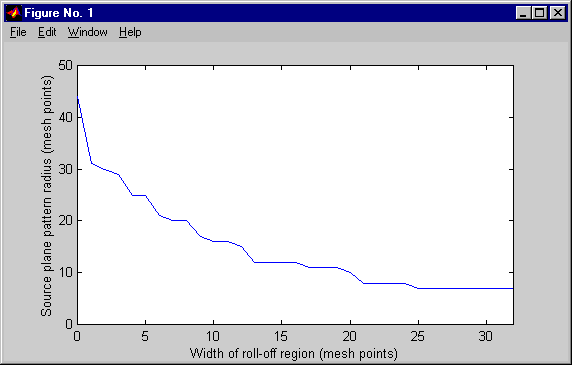
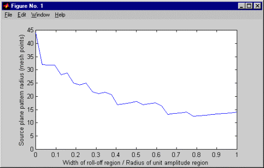
As one increases the width of the roll-off region, the maximum radius for a given tolerance tends to decrease in discrete steps, jumping from one Airy ring to the next smaller one. This effect is shown in the first figure below, where we used a tolerance of .01 in amplitude (equivalent to .0001 in intensity) and the two sigma gaussian roll-off shape. For a given size mesh, there is a tradeoff between the radius of the uniform amplitude region and the width of the roll-off region, because the sum of the two must be less than one fourth the width of the mesh. If we hold the sum of the two constant, while varying the ratio between them, we find that the width of the source pattern generally decreases as we increase the width of the roll-off region, but there are local minima, related to the discrete steps we saw before - see the second figure below. This suggests that it would behoove one to always choose a roll-off width corresponding to one of the minima, but that holds true only if there is some special significance about the tolerance chosen. If we change the tolerance, the minima shift. This raises the question of what tolerance we should use, or to put it another way, what field amplitude, as a fraction of the maximum, do we consider "negligible"? This depends upon the application. If we wish to model something like the ABLE ACE Differential Phase Experiment, which measured the differences between the fields received from two closely space point sources, we will need to be very careful, especially in the low turbulence limit. For all other applications, we suspect it is a minor issue.

Discrete transitions in source field radius as the width of the roll-off region is varied while the width of the region of uniform amplitude is held constant.

Local minima in the source field radius as the width of the roll-off region is varied while the total width of the region of nonzero field at the aperture plane is held constant.
This brings me to my recommendations:
1.Use the default method (back-propagation). In the PropagationController, the parameter "pointSourceModel" should be set to "DEFAULT_PSM".
2.Following the guidelines in choosing parameter settings for modeling optical propagation, determine the mesh spacing and mesh dimension you wish to use. (for ABL ACT, a good choice is dxy=.02 and nxy=256. For ABL, try nx =512, and dx >= sqrt(2*lamda*z / nxy), where z is the range.)
3.Pick a "super-aperture radius" - the radius for the uniform amplitude region - a "fair amount" larger than the system aperture. (At some point we should do a study determine how large this should be, as a function of the propagation scenario).
4.If the minimum acceptable super-aperture radius is bigger than half the mesh width, you need a bigger mesh. You could increase the mesh spacing, but if that would make it too coarse to capture the turbulence effects you will have to increase the mesh dimension.
5.The super-aperture radius should now be less than or equal to half the width of the mesh. If there is any margin, you can use it in two ways: increase the super-aperture radius, and/or create a roll-off region. In some cases the overall size of the mesh will be driven by sampling requirements, rather than the size of the super-aperture, so you may find that you have plenty of room for both. In such a case, we recommend you make the super-aperture radius 15% of the mesh width, and the roll-off region 10% of the mesh width. The roll-off shape will be the two-sigma gaussian, so sigma would be 5% of the mesh width. When space is tighter, reduce or eliminate the roll-off region.
To implement these decisions, you will need to use a PropagationController, the LightLike component that controls all parameters related to optical propagation. Propagation Controller has a total of ten parameters but just three of these are used to control point source modeling: pointSourceModel, superApertureRadius, andedgeSigma. pointSourceModel should be set to "DEFAULT_PSM". superApertureRadius defines the radius of the uniform amplitude region. edgeSigma controls the width of the gaussian roll-off region. 2*superApertureRadius + 4*edgeSigma should be less than half the width of the mesh. edgeSigma and superApertureRadius are also used in modeling optical "speckle", seen when coherent light illuminates an optically rough surface; see how speckle is modeled. The same considerations apply in both applications, so it is appropriate to use the same values of edgeSigma and superApertureRadius for both point source modeling and speckle modeling.
If you wish to use the other method LightLike supports for modeling point sources, where the initial field at the source plane has just a single nonzero mesh point, set the parameter pointSourceModel to "MESH_POINT_PSM". Depending on the propagation parameters, you may also need or want to use spatial filtering and/or absorbing boundaries, as described in how to use spatial filters and absorbing boundaries. In this case, the parameters superApertureRadius and edgeSigma are ignored for point source modeling, but they may still be used in modeling speckle, if there is any, depending on the speckle model chosen.
Other methods are sometimes used for modeling point sources. Some analysts create a field at the aperture plane whose amplitude is a "supergaussian", and then back-propagate that in vaccum to the source plane. Other analysts use a large gaussian at the aperture plane, which maps to a small gaussian at the source plane. Both of these methods are reasonable, but have the disadvantage that the expected value of the received amplitude at the aperture will vary somewhat as a function of the radial distance from the origin. LightLike does not presently support the supergaussian technique, but it can be reasonably well approximated by choosing of superApDiameter and edgeSigma appropriately. LightLike does support the use of pure Gaussians - simply set superApDiameter to zero, and use edgeSigma to control the size of the Gaussian.
