In order to work confidently with offsets, slews and other tilt-related modules, the user should have a basic understanding of how overall tilt is internally represented in LightLike. Some LightLike modules that add tilts to a wavefront offer the user a choice of methods for representing the tilt, while other modules offer no choice, using one method only. Consider the basic Tilt module, whose i/o and parameters are shown below left.
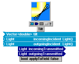
Notice the boolean (type "bool") parameter named "applyToField", which can be assigned the values "true" or "false". This offers the user a choice in how to internally represent the tilt angle that Tilt applies to the passing optical wave. If "applyToField" is set to "true", then the module will multiply the incident complex field by a phasor of the form exp[ ± i(2π/λ)(Δθx x + Δθy y) ]. If "applyToField" is set to "false", then Tilt will not apply the tilt phasor, but rather will add the present tilt increment to the so-called "tilt register" for the wave in question. Unless the user's application explicitly requires otherwise, the normal setting for "applyToField" should be "false" (note this is the default setting when the module is initially added to a system): it is almost always preferable to carry overall tilt information separately from the remaining complex field array.
The difficulty that arises when "applyToField" is "true", is that modest tilts can cause impractical sampling requirements for the numerical propagation mesh.
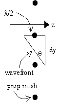
In a general LightLike diffractive propagation module, the incident complex field array (part of the "LightLike") is input to a Fresnel propagation operator. Suppose now that we wanted to explicitly apply a tilt of 100mrad to the phase of a plane wave of wavelength 1 mm, prior to applying the propagation operator. As shown in the sketch at right, to sample the initial tilted wavefront with even marginal adequacy would require a mesh spacing as small or smaller than dy = (l/2)/q = 5 mm. This spacing may be considerably denser than required by the other sampling constraints; furthermore, tilt angles of interest for LightLike problems can easily exceed this 100 mrad example. To avoid potentially severe sampling difficulties of this type, LightLike exploits a known mathematical property of the Fresnel propagation operation. If one applies the Fresnel propagator (along z) to a wavefront with a specified tilt factor, the resulting complex field is exactly equal to that obtained by propagating the tilt-removed field, shifting that result transversely, and finally applying a tilt phasor. The latter method is what LightLike uses when "applyToField" = "false" in Tilt and similar modules.
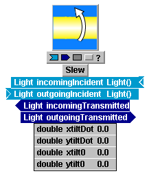
By way of contrast to Tilt, there are some closely related modules where the user is given no choice regarding the internal tilt representation. For example, the Slew module, which is illustrated on the right side of the previous diagram, is at the LightLike code level simply a time-varying Tilt. However, from the i/o and parameter lists, we see that Slew provides no "applyToField" option: LightLike automatically uses the concept "applyToField" = "false" in Slew. The following section further discusses the connection between tilt representation and the required size of the numerical propagation mesh.