LightLike assumes that all optical beams propagate at small angles relative to the z axis. Beams may propagate in the (+z) or (-z) directions. Any physical sequence of optical components that fold or refract light through large angles (such as steering mirrors) should be visualized in terms of an unfolded path, as far as the LightLike model is concerned. Every LightLike module (subsystem) has a local (x,y,z) coordinate system, and characteristics such as aperture support and source module beam profiles are defined with respect to their respective local coordinate origins. In the absence of explicitly imposed transverse displacements, each module (subsystem) in a LightLike system has its local coordinate origin on the z axis of a conceptual global coordinate system. We emphasize the word conceptual, because LightLike does not actually assign global z coordinates: the only z distances actually input into LightLike are propagation distances, |Δz|, between modules. More precisely, these |Δz| are the distances between the local origins of two modules. The direction (positive or negative) associated with |Δz| is specified by "outgoing" and "incoming" tags as described below.
Propagation distances |Δz| are specified in the inputs or parameters of propagation modules such as AtmoPath or VacuumProp. As will be explained soon, it is also typical in wave-optics modeling to have many optical-system components with zero separation. Zero separation between neighboring modules is assumed, whenever no |Δz| is explicitly specified.
When constructing LightLike models, users must clearly understand some specialized directional nomenclature used by LightLike. Three key pairs of terms are used everywhere in LightLike with specialized meanings. These terms are "Incident/Transmitted", "Outgoing/Incoming" and "Platform/Target".
"Incident" and "Transmitted" tags
As explained above, the physical sequence of optical components modeled in LightLike should be visualized in terms of an unfolded path. Any beam that enters a LightLike module is called "Incident", and any beam that exits a module is called "Transmitted". In particular, a LightLike "Transmitted" beam can refer to light that was physically reflected, transmitted or internally generated (by a source). For examples of incident and transmitted tags, see the input/output bars (the light and dark blue bars) in the System Editor picture below.
"Outgoing" and "Incoming" tags: orientation of +z
Positive- and negative-z directions are defined in LightLike via the "outgoing" and "incoming" tags that appears in the input/output lists of various propagator and other modules. The (+z) direction is identified with the "outgoing" direction tag, and the (- z) direction is identified with the "incoming" direction tag. For example, the figure below shows two separate systems consisting of a PointSource source and a TargetBoard sensor connected via the AtmoPath module.
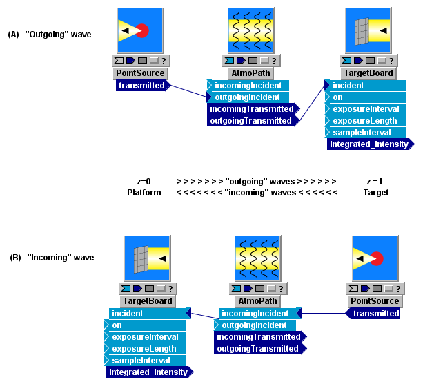
In system (A), the wave emerging from PointSource is connected to the "outgoingIncident" input of AtmoPath. Consequently, the wave traveling from PointSource to TargetBoard is defined to be traveling in the (+z) direction. Usually, it is acceptable to think of PointSource as located at z=0 and TargetBoard as located at z=+L, although this is not literally what LightLike does internally. As stated previously, LightLike only works with z differences between or across modules. The absence of an absolute 0 of z is significant if one works with a LightLike system that contains several (i.e, more than one) concatenated atmospheric modules. In that case, the z-coordinates of phase screens within each atmospheric module refer to relative positions within that atmospheric module only.
In system (B), the wave emerging from PointSource is connected to the "incomingIncident" input of AtmoPath. Consequently, the wave traveling from PointSource to TargetBoard is defined to be traveling in the (- z) direction. We can think of TargetBoard as located at z=0 and PointSource as located at z=+L, with the caution mentioned above. In general, both outgoing and incoming waves can be present in a single system.
The visual layout (right-left, top-bottom) of the subsystems in the System Editor has absolutely nothing to do with establishing (+z) and (-z) directions. The only thing that matters are the "outgoing" and "incoming" tags established by certain of LightLike's subsystems. In the above example systems (A) and (B), we positioned components so that an outgoing wave (+z) points to the right, and an incoming wave (-z) points to the left, but that was solely to help in human visualization.
In the above examples, AtmoPath provided the outgoing/incoming assignments. If AtmoPath is not included in a LightLike system, there will usually be some other module that establishes the assignments "outgoing" (+z) and/or "incoming" (-z). However, not all LightLike modules that deal with wave inputs or outputs need to designate the input/output as outgoing or incoming. For example, we see in the preceding picture that PointSource simply generates a wave designated as "transmitted", without specifying whether that means outgoing or incoming. Whether a module needs to know that a wave is outgoing or incoming depends on the mathematical operation that module will perform on the complex field.
Side remark regarding GUI manipulation: In the preceding diagram, notice that in system (A) the inputs all have their triangle connectors on the left sides of the modules, whereas in system (B) the input connectors are all on the right sides of the modules. The output connectors stand in an analogous relation. This flipping of inputs or outputs is accomplished by right-clicking on a module, and then choosing the "Flip inputs(outputs)" command (double-clicking on the input or output bar does the same thing). Flipping is not necessary to make the system function, but it greatly improves the graphical readability.
"Platform" and "Target"
As described above, the system connections to "outgoing" and "incoming" input/output boxes are the only determinants of positive and negative z direction. Additionally, at many places in the LightLike documentation, the terms "platform" and "target" are used in the following specialized directional sense:
"Target" means the more-positive z end of the system (the destination of "outgoing" waves or the source of "incoming" waves), while
"Platform" means the more-negative z end of the system (the destination of "incoming" waves or the source of "outgoing" waves).
The user should realize that the terms "platform" and "target" never appear in any of the objects that are manipulated in TimeLike System Editor window. The only directional specifications that the user directly designates when building a system are "outgoing" and "incoming". "Platform" and "target" ends can both contain sources, sensors or reflectors: there is no restriction in that regard. The additional "platform-target" terminology may initially seem redundant or confusing, and may conflict with what is really the physical target of a beam in a particular application. However, this terminology is now thoroughly ingrained in LightLike documentation and usage.
X and Y axes
LightLike's x and y axes are two Cartesian axes transverse to the z axis, where the latter is always the nominal propagation direction. There is no intrinsic relation between LightLike's (x,y,z) directions and any earth-connected coordinate system. There is no intrinsic association with up, down, right, left, horizontal or vertical. Each LightLike module has its local x-y coordinate system, and the defining characteristics of the module (e.g., aperture boundary, focus aberration curvature factor, position offset, etc.) are all defined relative to that local x-y coordinate system. The local z axes (or x-y origins) of different modules are either colinear with each other or transversely offset from each other, as determined by the insertion (or not) of a TransverseVelocity module. The important topic of transverse displacement and transverse motion is discussed in further detail in a later section.
In many LightLike modules, there is no explicit specification of how the defining characteristic (e.g., Aperture boundary) is offset with respect to the local x-y origin. If there is no explicit specification, the user should assume that the characteristic in question is centered with respect to the local x-y origin.
Transformation of outgoing to incoming waves
As stated previously, mirror-like deflections in LightLike are modeled in terms of an unfolded optical system. Typical examples would be a beam incident on a Tilt module or on a BeamSteeringMirror module. For example, if a wave is fed to the "outgoingIncident" input of a Tilt module (see panel (A) of the following diagram), then the corresponding output beam is obtained from the "outgoingTransmitted" output of the Tilt module. An incoming wave ("incomingIncident" and "incomingTransmitted" may also be controlled by the same Tilt block, as represented by the dashed arrows in (A). This models a common situation in a laser beam projection system, where the same steering mirror might affect a projected laser beam heading toward a target, as well as beacon light returning from the target. What is not allowed is the operation shown in panel (C): one may not transform the outgoing beam to an incoming beam simply by making the connections illustrated in (C).
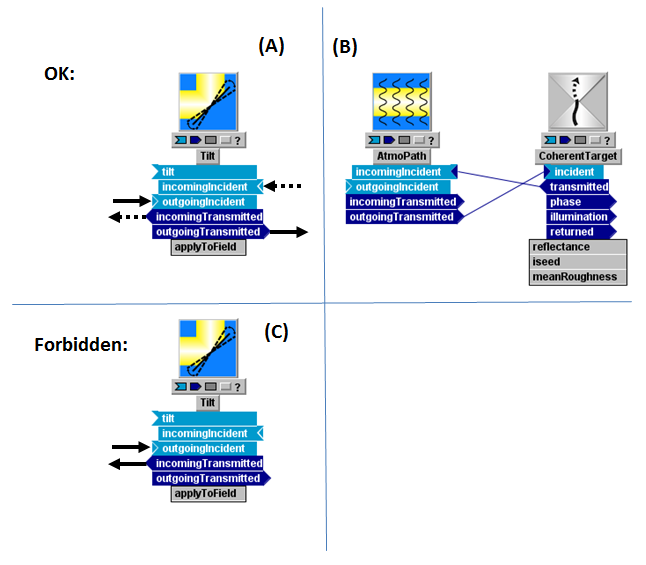
This restriction applies to all LightLike modules, but there are a few specialized reflector components that mayappear to transform outgoing to incoming waves (or vice-versa). Among these are the rough-reflector modules like CoherentTarget, IncoherentReflector, or PartiallyCoherentReflector. Panel (B) of the above figure illustrates this idea. The decision to connect CoherentTarget's "transmitted" output to AtmoPath's "incomingIncident" input seems logical, since most often we want the reflected ("transmitted" in LightLike terminology) beam from this component to propagate back in the opposite direction through the same atmospheric screens that the incident beam saw (possibly displaced in x or y, of course). Thus, CoherentTarget and similar modules have the apparent capability of transforming {outgoing ↔ incoming}. However, what such modules are really doing is acting as both "sensors" and "sources": one should think of the module's "transmitted" LightLike as being a new LightLike that was generated by a source. Therefore, this type of module's "transmitted" LightLike can be connected to either a subsequent "incoming" or "outgoing" tag. For example, if the CoherentTarget in panel (B) was meant to model a transmissive ground-glass plate, with subsequent propagation through a second atmospheric path, then it would make sense to add a second AtmoPath module to the right of CoherentTarget, and to connect CoherentTarget's "transmitted" output to the "outgoingIncident" input of that second AtmoPath.