The subsystems of a LightLike model can typically be grouped into functional groups that represent either propagation channels or optical system groups. The latter might represent transmitters, targets, or receivers. The optical system groups share one critical characteristic: it is often desirable, in wave-optics modeling, to ignore physical propagation between the components of an optical system group. All the components of a single optical system group can be modeled as operating in a space of common transverse magnification, which is usually taken as having the same transverse scale as the propagation channel. Equivalently, this transverse scale would correspond to the entrance pupil in case of a pure receiver or the exit pupil in case of a pure transmitter. For brevity in this documentation we refer to this space as the "object" space. In this modeling approach, which considerably simplifies the model bookkeeping, we specify the parameters of each optical component transversely scaled to the object space, and we usually place all the optical components in a common z plane, with zero separation between the components. In this approach, the optical system component parameters are immediately related to the turbulence and propagation parameters of the propagation medium. A wide variety of phase and amplitude map manipulation, beam splitting, detection processes and adaptive-optics feedback loops can still be accurately modeled in such a collapsed model of the optical system. The order of operations carried out by various elements (splitting, attenuating, tilting, sensing, etc.) corresponds to the order in which the LightLike blocks are connected, and this must be consistent with the actual order in the physical system. With one exception, in most LightLike modeling there is no reason to carry out physical-optics propagation using Fresnel propagators within the optical system. The one exception is computation of the far-field image in (or near) a focal plane, which is carried out in LightLike's Camera and HartmannWfsDft(wavefront sensor) modules. In these special case, the diffractive effects of the entrance pupil are accounted for by far-field propagations embedded in the modules. Defocused sensor planes can be accounted for as well in this framework. The omission of diffractive propagation between most elements of the optical system is consistent with the usual optical analysis of composite systems: the effects of diffraction are for practical purposes completely represented by one physical propagation from pupil to sensor plane.
The following figure shows a simple detector system that illustrates the above points.
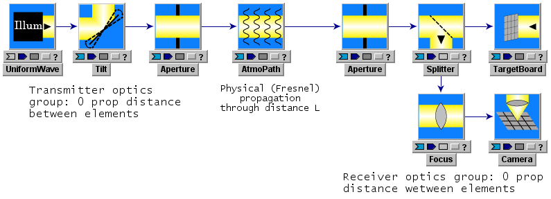
Consider the receiver optics group. Within this group, there are no subsystem inputs or parameters that specify separations between any of the subsystems. Consider first the receiver actions comprising truncation by Aperture, "splitting" or more accurately "copying" of the beam by Splitter, discrete sampling on a sensor mesh by TargetBoard, and the application of a quadratic phase by Focus. All these mathematical operations are applied to the incident complex field in the same z-plane, namely the z-plane of the aperture. The order of the operations is faithful to the connection arrows in the picture. Now the physical system that is being modeled will of course have non-0 separations between the receiver elements, and may in fact include various reimaging and demagnification stages. For example, the targetboard may model a CCD sensor on which is physically impinging a demagnified image of the physical aperture plane. As long as diffractive effects due to the reimaging optics are negligible, accurate modeling can be done by projecting the mesh spacing of the physical CCD sensor to the aperture plane. This projection to the "object space" is the usual way that optical systems (both transmitters and receivers) are simplified for modeling in LightLike (or any other wave-optics code) .
The Camera module in the receiver group does internally incorporate a key physical propagation. The action of Camera is to compute the diffractive far-field (Fraunhofer) irradiance corresponding to whatever input complex field is presented to Camera. In this case, diffraction by the receiver group's Aperture has a dominant effect on the irradiance distribution in the Camera sensor plane, and this diffraction is completely accounted for by the internal computations of Camera. The particular combination of geometric and physical (diffractive) propagation outlined here is very typical in the analysis and numerical modeling of optical systems. If the combination of projections to object space plus far-field Cameras is insufficient to accurately model a given optical system, then it is possible to construct a system that actually computes physical propagations between numerous optical elements. The key difficulty is properly generating the widely varying propagation mesh spacing required as the optical beam undergoes a sequence of possibly large compressions or expansions. This will usually require understanding and use of the "spherical reference wave" feature of LightLike's Fresnel propagator modules.
Side remark: The Focus system in the above receiver group illustrates a secondary point. A typical application of Focus in a receiver group is to allow a Camera focal plane to be the image plane conjugate to a finite (rather than infinite) distance. The composite LightLike module called Telescope may also be used for this purpose. See "Using the Camera module" for further discussion.
Complete systems with 0 total propagation distance
For testing purposes, it is often very useful to construct a complete LightLike system that has no propagation distance anywhere in the system (except possibly inside a Camera module). The only caution to be observed here is that one must be careful to actually specify the mesh on which the optical field is defined. In a typical LightLike system this might be accomplished by the propnxy and propdxy parameters in the AtmoPathsubsystem. However, in the absence of any propagator module, the recommended procedure is to insert a PropagationController subsystem to define the mesh parameters on which the optical field is generated. Normally, one or more PropagationControllers are automatically present because they are subsystems of propagation modules such as AtmoPath. See the section devoted to PropagationControllers for further discussion.
The following figure shows an example of a complete system with 0 total propagation distance: the system tests the operation of a wavefront sensor by presenting it with a perfect plane wave of variable tilt and focus.
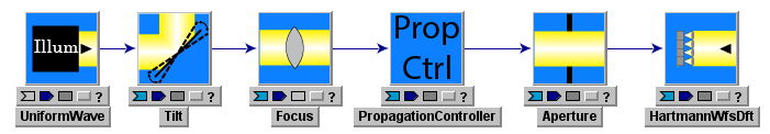
Note that LightLike sources such as UniformWave and GaussianCwLaser make sense when the total propagation distance is 0, but the action of LightLike's PointSource is ill-defined if we have no propagation distance.