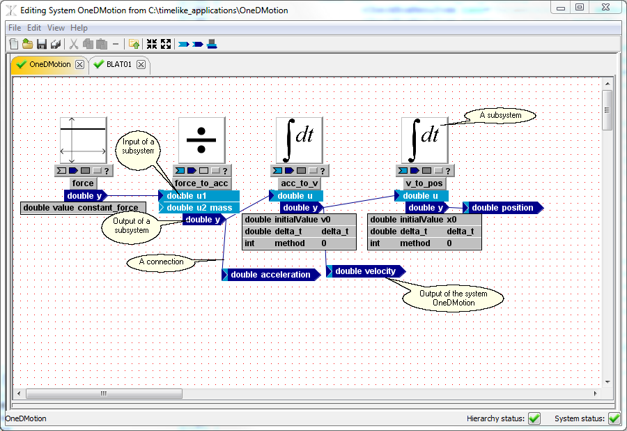
The Block Diagram Editor is where you do all your editing work. You will spend most of your time here navigating your model hierarchy, adding, removing and connecting subsystems, inputs, outputs and parameters. The user can navigate into a subsystem by double-clicking its icon and navigate up by double-clicking in the white space. As the user navigates through the hierarchy, the System Properties section changes to reflect system that is currently being displayed in the Block Diagram Editor.
NOTE: many operations are available via context menus that are displayed when the user right-clicks on objects or on the white space.
Navigation through the Model Object Hierarchy
•Double-click a subsystem's icon (or right click an icon of subsystem and select "Open") to go inside a system.
•Double-click on white space (or click button ![]() on the toolbar or in the block-diagram context menu) to navigate up the hierarchy.
on the toolbar or in the block-diagram context menu) to navigate up the hierarchy.
Objects in the Block Diagram Editor
Parameters, Inputs, Outputs, Blank Subsystems and Notes
•Parameters are variables used to fine-tune the behavior of each instance of a particular system, and/or to define its initial conditions. A parameter of a system doesn't have visual representation in the Block Diagram Editor and can only be edited or removed via System Properties Editor.
•An input is a part of the external interface of a system or system class, used to define how a system’s environment can act upon the system. An input (with type 'double', name 'u' and value '1.0' ) of a system is represented as ![]()
•An output is a part of the external interface of a system or system class, used to define how a system can act upon its environment. An output (with type 'double', name 'u' and value '0.0' ) of a system is represented as ![]() . A triangle in the "tail" indicates that the output has a default value that is used when output is not connected.
. A triangle in the "tail" indicates that the output has a default value that is used when output is not connected.
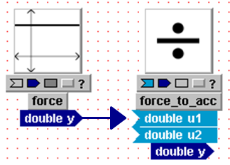
•A subsystem is a system which is used as part of a larger system or system class.
•A connection is a relationship established between an object used to refer some other object, e.g. a subsystem input, and another object which serves as the referent for the first object, e.g. a subsystem output. Connections are represented graphically in the GUI as arrows from the referent objects to the reference objects.
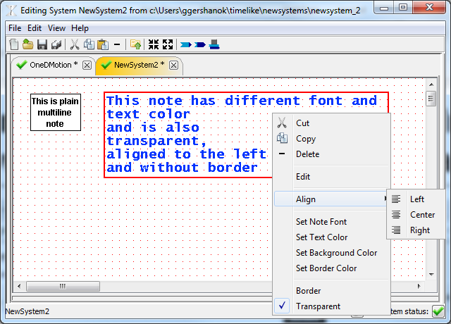
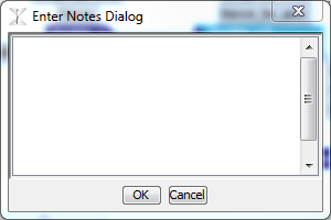
•A note is a multi-line text (with standard graphical properties such as font and color) that is used for annotating a block diagram.
General Operations in the Block Diagram Editor
All objects in the Block Diagram Editor can be added, selected, removed, copied, edited via right-click context menu or via keyboard shortcuts (such as <Del>to remove objects and <Ctrl-C> / <Ctrl-V> to copy/paste selected objects.
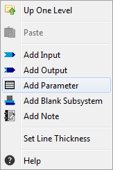
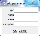
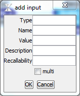
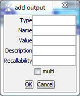
•To add a parameter, an input, an output, a blank subsystem or a note, right-click on white space in the Block Diagram Editor and select corresponding menu item. A corresponding dialog will be displayed. Enter all the required information and click "OK".
•To select an object just click it or lasso around it. To select multiple obejcts - hold <Ctrl> key down while clicking or lassoing.
•There are several ways to remove selected object or objects:
ohit <Delete> key on the keyboard
oright-click on any of the selected objects and select "Delete" from the context menu
oclick "-" button on the toolbar
oSelect "Delete" from the "Edit" menu.
•Cut/Copy/Paste of selected objects is available via "Edit" menu, toolbar or as standard keyboard shortcuts.
Object-Specific Operations in the Block Diagram Editor
•double-click an input to flip it. The input changes its shape from ![]() to
to ![]() .
.
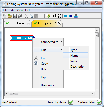
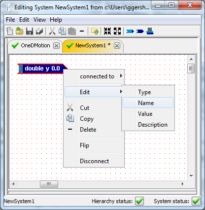
•Right-click an input to display context menu to view connected objects (if input is connected), edit type, name or value of an input, flip or disconnect it.
•double-click an output to flip it. The output changes its shape from ![]() to
to ![]() .
.
•Right-click an input to display context menu to view connected objects (if input is connected), edit type, name or value of an output, flip or disconnect it.
•double-click an icon to go inside subsystem. Going inside is necessary to edit the interface and implementation of a subsystem.
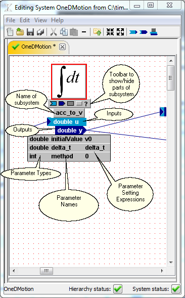
•Use the toolbar to show/hide Subsystem's name, inputs, outputs and parameters.
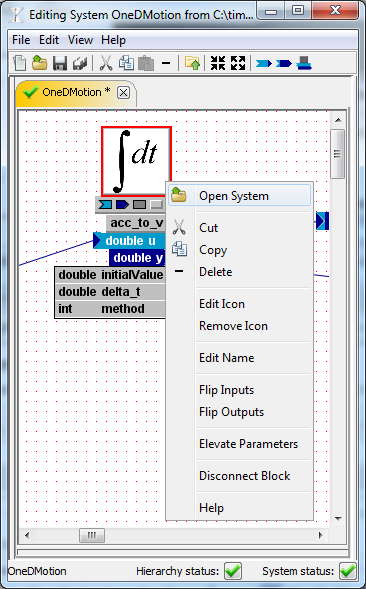
•Right-click the subsystem's icon to display Subystem's context menu
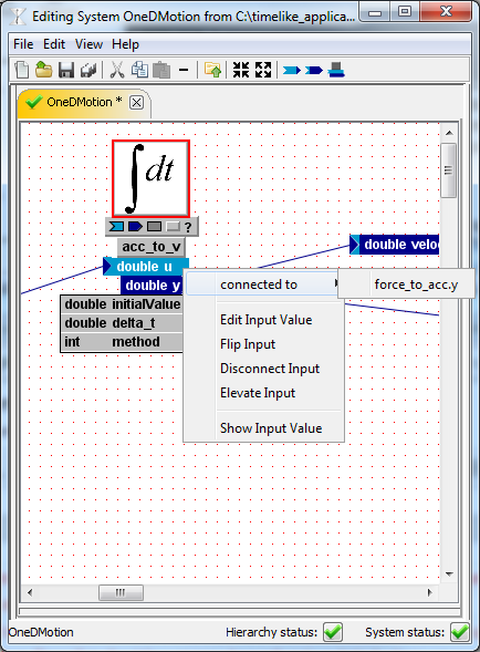
•Right-click subsystem's input to display Subsystem's input context menu
•Right-click subsystem's output to display Subsystem's output context menu

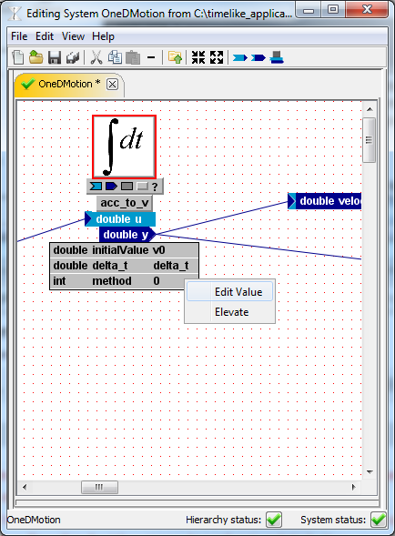
•Right-click subsystem's parameter to display Subsystem's parameter context menu
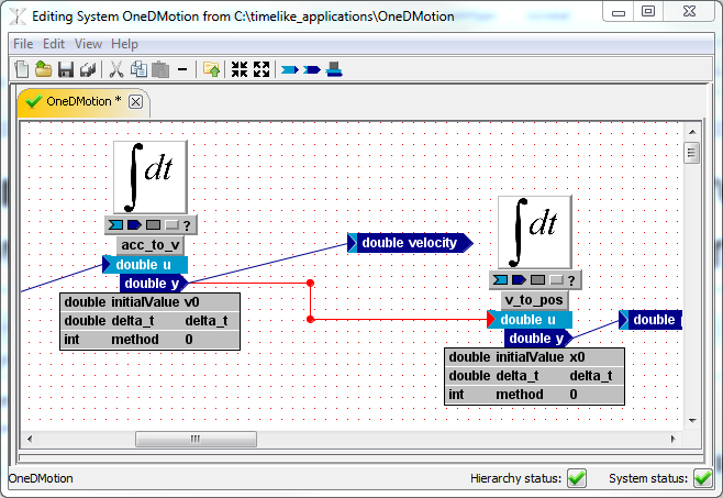
•To connect output to an input, drag & drop the arrowhead from an output onto an input
•click on a line to add a vertex
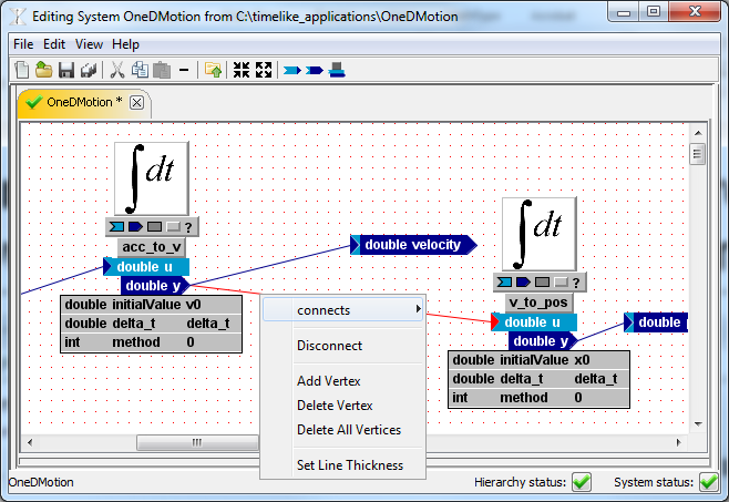
•right-click on a line to display the connection's context menu
•Right-click on a note to display its context menu.