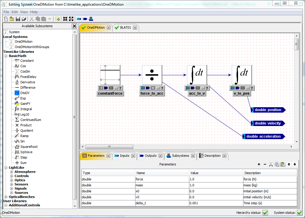
The main section of the System Editor Window is a Systems Panel that can hold multiple System Panels - one for each Reusable Component loaded for editing. For example, the Systems Panel shown below has two models loaded: OneDMotion and BLAT01. Each System Panel contains Block Diagram Editor and System Properties Editor.
The Block Diagram Editor
The Block Diagram Editor is where you do all your editing work. You will spend most of your time here navigating your model hierarchy, adding, removing and connecting subsystems, inputs, outputs and parameters. The user can navigate into a subsystem by double-clicking its icon and navigate up by double-clicking in the white space. As the user navigates through the hierarchy, the System Properties section changes to reflect system that is currently being displayed in the Block Diagram Editor.
NOTE: many operations are available via context menus that are displayed when the user right-clicks on objects or on the white space.
System Properties Editor
The System Properties Section represents system's parameters, inputs, outputs, and subsystems as tables for convenient viewing and editing. System Properties section reflects the system that is currently being displayed in the Block Diagram Editor. The user can close any panel in the System Properties Section by clicking 'x' icon on a tab header. A panel can be reopen via "View" menu.
NOTE: Some operations can only be done via either Block Diagram Editor or System Properties Panel, and some can be done in both. For example, system parameters and system description can only be edited via System Properties Panel, but connecting or disconnecting inputs and outputs only via Block Diagram Editor.
System Properties Section
The System Properties Section represents system's parameters, inputs, outputs, and subsystems as tables for convenient viewing and editing.