In the section on basic properties of sensor modules, we explained that the LightLike sensors all provide point samples on the specified detector mesh. If the field incident on the detector mesh plane has significant spatial variations, and if the physical pixel size to be modeled does not resolve those variations, then it is usually necessary to perform spatial integration over the physical pixel size in order to obtain the desired modeling result. The LightLike library system provided for that purpose is called SensorNoise. The name may seem inappropriate, but this system does double duty: the optional addition of various kinds of detection noise is a second capability of this module. The following diagram shows the interface of SensorNoise:

As we see in the interface picture, the input to SensorNoise is assumed to be an integrated intensity: this will usually be the output of one of LightLike's intensity-sensor modules, such as TargetBoard, Camera, or HartmannWfsDft. The output of SensorNoise, called detectorCounts, will be in units of digital counts. At the end of the present section, we make some remarks regarding the units conversion, but our immediate focus is on the spatial integration feature.
The basic concept used by SensorNoise to set up the spatial integration is the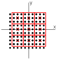 specification of a new mesh, whose points represent the centers of the physical pixels. This new mesh is specified by the parameter detectorGrid. A concrete example may be helpful. In the diagram at right, there is mesh indicated by black dots. Suppose this is the output mesh of a TargetBoard or Camera module, and that this is the mesh on which SensorNoise's input integratedIntensity is given. Next, suppose that we are interested in the response of a physical sensor whose pixel width is three times the black-dot mesh spacing. The boundaries of the physical pixels are indicated by the red lines. In order to specify these physical pixels to LightLike, we must define the detectorGrid mesh to be the center points shown as red crosses. Since the detectorGrid parameter has data type "GridGeometry" (see column 1 of the parameters list), we must use one of several special LightLike library functions to define the new mesh. In the above picture of the SensorNoise interface, we have entered a setting expression that uses the "gwoom" function: gwoom(3,dxyinput*3.0). The first function argument signifies the mesh dimension of the new mesh, and the second argument signifies the mesh spacing of the new mesh. (The symbol dxyinput would have to be elevated or replaced locally by a number.) For further background and all the options for mesh specification, see the introduction to meshes and the detail section on the functions gwoom and GridGeometry.
The spatial integration in SensorNoise uses a fairly sophisticated interpolation and integration procedure to produce sensible integration results regardless of the offset between the input and output meshes. The picture above shows a nice symmetric registration between the two grids, but the integration algorithm is designed to handle general cases. If users wish to do the spatial integration personally, by a specific algorithm of their choice, then they must work this in post-processing or alternatively create a user-defined LightLike component.
Units conversion and noise features
Noise generation in SensorNoise can be turned off by setting the addNoise parameter to false (see the interface picture). However, the conversion to digital counts cannot be turned off. The parameter maxCountpresents a potentially tricky limitation. Since its data type is integer, the maximum possible digital counts value is 231-1. While usually adequate for physically realistic inputs, there will be a problem if, for example, the user scales the responsivity to count photons together with a long enough integration time.