This section reviews each entry field in the AO Geometry Parameters dialog window, and specifies some details not discussed previously. As seen in the previous examples, the dialog window is separated into three parameter specification sections (Actuator Geometry, Subaperture Geometry, and Influence Function) plus a control buttons section at the bottom of the window. The entries in the parameter specification sections determine the geometry of the system, the relationship of slave to master actuators, and the type of influence function.
Actuator geometry entries
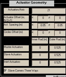
Actuators/Axis: The actuators are assumed to be distributed on a rectangular (usually square) mesh clipped by an annular region. Actuators/Axis is usually set to the number of actuators across the widest part of the aperture. This figure should include all actuators master, slave, and inert. A conventional choice would be to place an actuator at the origin, with two lines of actuators lying on the x and y axes and the remaining actuators distributed symmetrically about the x and y axes: to do this, begin with Actuators/Axis = odd integer.
Actuator Offset: Specifies the (x,y) offset, in meters, of the center of the actuator mesh from the local (x,y) origin. If Actuators/Axis is odd, the "center of the actuator mesh" corresponds to the center actuator. If Actuators/Axis is even, the "center of the actuator mesh" is halfway between the two middle actuators.
CAUTION: regarding alignment between actuators and subapertures, see the background section for comments on asymmetry and misregistration.
Act. Spacing: Specifies the x and y spacing, in meters, between actuators. The x and y spacings are usually, but not necessarily, made equal. As discussed previously, this specification is usually made in object space coordinates.
Circles Offset: The radii specified below define circles nominally centered at the local origin. "Circles offset" provide a means to shift the centers of these circles relative to the local origin. All offsets and radii are specified in meters.
Various Actuator Radii: In specifying the actuator geometry, the user sets up annular regions used to indicate boundaries for different types of actuators. These regions are superposed on the mesh of actuators and used to clip or type each actuator. For each type of actuator there are two radii. Let rmaster and Rmaster be the inner and outer radii of the master actuators, respectively. Similarly let rslave, Rslave, rinert, and Rinert be the inner and outer radii of the slave and inert actuators. The system must be set up such that
Rinert >= Rslave >= Rmaster > rmaster >= rslave >= rinert >= 0.
Given the array of actuators and the offsets defined above, all actuators falling outside the circle of radius Rinert or inside the circle of radius rinert are eliminated from the configuration. Actuators falling between Rinert and Rslave and rinert and rslave are deemed inert actuators. Actuators falling between Rslave and Rmaster and rslave and rmaster are deemed slave actuators. Finally, actuators falling between Rmaster and rmaster are identified as master actuators.
Note in particular that if Rinert=Rslave , then there will be 0 inert actuators at the outside edge of the mirror. Likewise, if rslave=rinert, then there will be 0 inert actuators in the inner annulus.
Slave Corners Three Ways: aogeom provides two ways of automatically setting up master-slave relationships depending on slave and master adjacencies. When the 3-ways box is not checked, slaves which are on a corner adjacent to three actuators, one vertically, one horizontally, and one diagonally, are only slaved to the horizontal and vertical actuators. If the slave is on a side which is vertically or horizontally adjacent to one master and diagonally adjacent to two actuators, the actuator is slaved only to the vertical or horizontal master. In the annular region, the slaving occurs in such a way that horizontal and vertical slaves are favored and diagonal slaves are not used if a horizontal and/or vertical masters are available. When the 3-ways box is checked, slave actuators are slaved to every adjacent master actuator, vertical, horizontal, and diagonal.
Subaperture geometry entries
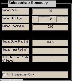
Subaps./Axis: The subapertures are assumed to be distributed on a square mesh clipped by an annular region. Subaps/Axis is usually set to the number of subapertures across the widest part of the aperture. A conventional choice would be to begin with Subaps/Axis equal to one less than Actuators/Axis.
Subap. Offset: Specifies the (x,y) offset, in meters, of the center of the subaperture mesh from the local (x,y) origin. If Subaps/Axis is even, the "center of the subaperture mesh" is a corner where four subapertures meet. If Subaps/Axis is odd, the "center of the subaperture mesh" is the center of the middle subaperture.
CAUTION: regarding alignment between actuators and subapertures, see the background section for comments on asymmetry and misregistration.
Subap. Spacing: Specifies the x and y spacing, in meters, between subaperture centers. Only equal x and y spacing is allowed for the subapertures. Furthermore, the width of the subapertures is assumed equal to the spacing (i.e., 100% fill factor). To deviate from the 100%-fill square subapertures, see the comments in the background section. As discussed previously, this specification is usually made in object space coordinates.
Subap. Radii: In specifying the subaperture geometry, the user sets up annular regions used to indicate boundaries for the subapertures. These regions are superposed on the mesh of subapertures and used to clip the subapertures. Let rsubap and Rsubap be the inner and outer radii of the master actuators, respectively. Subapertures which fall outside Rsubap or inside rsubap are eliminated. Usually rsubap and Rsubap are approximately equal to Rmaster and Rmaster because it is natural to set up the AO system so that master actuators are at the every corner of every subaperture. In fact, reconstructors computed for systems which contain a master actuator not located at the corner of a sufficiently-illuminated subaperture or a slave actuator at the corner of a sufficiently-illuminated subaperture will be poorly conditioned.
# of Integ. Steps/Side of Subap.: When computing the slope influence function, aoinf numerically evaluates the G-tilt formula over a subaperture area. The integration rule that is used requires the parameter "# of Integ. Steps/Side of Subap." to be EVEN. Six or eight should be sufficient to represent the shape of a deformed mirror over the region of a subaperture.
Full Subapertures Only: This selection determines the method of excluding and including subapertures within the specified subaperture radii. When this option is not selected, any subaperture whose area lies mostly between the inner and outer subaperture radii will be included. When this option is selected, only subapertures whose area falls completely between the radii are included.
Influence function entries
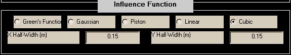
In this section of the Parameters window, the user specifies the shape and extent of the single-actuator influence function. The user has the choice of five shapes: Green's Function, Gaussian, Piston, Linear, and Cubic. For each shape the user is prompted for two parameters that define the effective width of the influence function. This section describes each influence function shape and the corresponding width parameters. To choose a particular influence function shape, the user chooses the appropriate button, and then enters the width information in the resulting editable text boxes. Since the Green's function influence shape is directly based on a physics equation that describes the mechanical properties of a flexible plate, it is probably a more accurate representation than the empirical options (gaussian, piston, linear, cubic). However, if the width parameter is not well known, then the superiority of the Green's function shape over some of the empirical ones is questionable.
Except for the Green's Function clamping radius, the specification of the influence function has no impact on the graphical representation of the AO system geometry. It simply sets up input parameters which are used by aoinf in its calculation of the influence function matrices. So, as far as calculations are concerned, the following description of the influence functions is more relevant to aoinf rather than aogeom. Nevertheless, we classify the specifications as geometry information, and therefore the specs are entered in the aogeom GUI.
Green's Function:
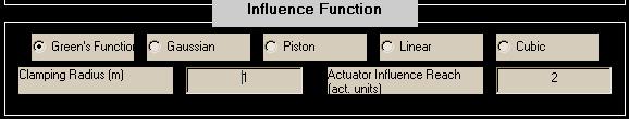
The so-called "Green's function" influence function in aoinf is derived from the solution of a clamped-plate partial differential equation (Balakrishnan). The user specifies two input parameters:
(1) the clamping radius, rclamp, in m
(2) the number of actuators away that a given actuator affects ("actuator influence reach"), in actuator units.
Beyond this reach, the influence function is assumed to be identically zero: this is a practical concession to limit the size of the influence function matrix. Since the Green's function influence shape is directly based on a physics equation that describes the mechanical properties of a flexible plate, it is probably a more accurate representation than the empirical options (gaussian, piston, linear, cubic) described below. To date, the Green's Function shape has been the choice most commonly used by modelers when applying LightLike.
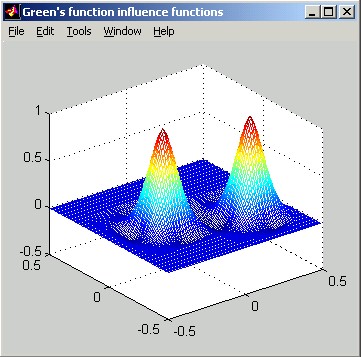
The following slice plot shows Green's influence functions far from the clamping radius and near the clamping radius. The spacing between actuators is 0.15 m, and the actuator influence reach is 2 actuators. The horizontal distance scale of the slice plot is in meters. The vertical scale can be interpreted as relative: the poked actuator has been displaced by 1 unit.
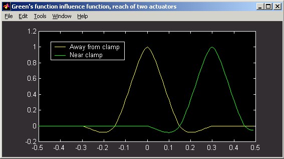
Notice that the negative deflection of the surface on the right side of the actuator near the clamp is different than the deflection far from the clamp. Although clamped DMs appear to be a thing of the past, this formulation can still be used for modern DMs by specifying rclamp >> rinert , to model an essentially unclamped DM. Qualitatively, the Green's function solution differs from all the other influence function options in that it produces negative deflection lobes at certain distances from the force application point.
The two pictures below show image-plot and perspective-plot representations equivalent to the above slice plot.

REFERENCES:
A.V. Balakrishnan, "Shape control of plates with piezo actuators and collocated position/rate sensors", Applied Mathematics and Computation, vol. 63, pp. 213-234, 1994.
Gaussian:
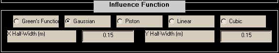
Gaussian influence functions implement the form:
d = exp(-Δx2/wx2) * exp(-Δy2/wy2)
where
wx is the X Half Width at the 1/e point, specified by the user in aogeom,
wy is the Y Half Width at the 1/e point, specified by the user in aogeom,
Δx is the distance in x from the poked actuator, at the point where the surface deflection is to be determined,
Δy is the distance in y from the poked actuator, at the point where the surface deflection is to be determined,
d is the surface deflection at the point located (Dx,Dy) from the poked actuator.
Usually, w = wx = wy , which, for Δr2 = Δx2 + Δy2 means:
d = exp(-Δr2/w2).
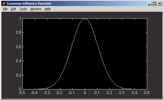
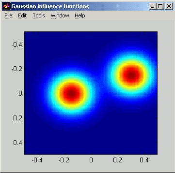
The following figures illustrate Gaussian influence functions. The horizontal distance scale of the slice plot is in meters. The vertical scale can be interpreted as relative: the poked actuator has been displaced by 1 unit.

Piston:

Piston influence functions implement the form:
d = 1 when |Δx| < wx and |Δy| < wy, and 0 otherwise
where
wx is the X half-width specified by the user in aogeom,
wy is the Y half-width specified by the user in aogeom,
Δx is the distance in x from the poked actuator, at the point where the surface deflection is to be determined,
Δ y is the distance in y from the poked actuator, at the point where the surface deflection is to be determined,
d is the surface deflection at the point located (Δx,Δy) from the poked actuator.
The following figures illustrate Piston influence functions. The horizontal distance scale of the slice plot is in meters. The vertical scale can be interpreted as relative: the poked actuator has been displaced by 1 unit.
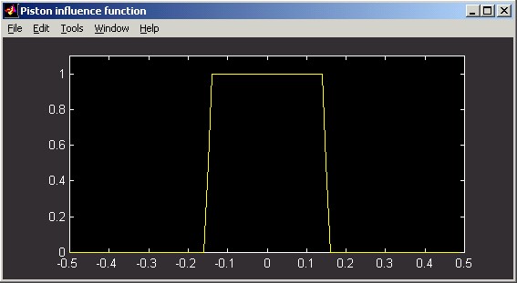
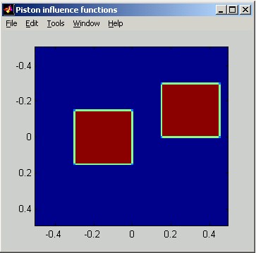
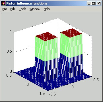
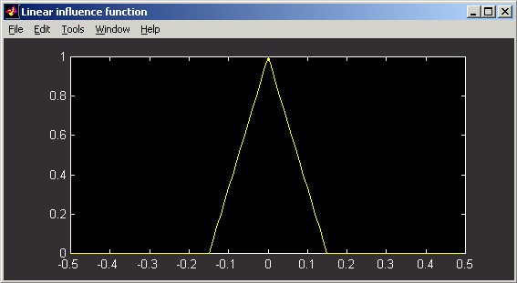
Linear:
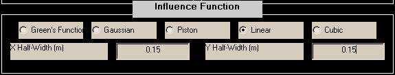
Linear influence functions implement the form:
d = (1 - |Δx|/wx) * (1 - |Δy|/wy), when |Δx| < wx and |Δy| < wy, and 0 otherwise,
where
wx is the X half-width (to the zero point) specified by the user in aogeom,
wy is the Y half-width (to the zero point) specified by the user in aogeom,
Δx is the distance in x from the poked actuator, at the point where the surface deflection is to be determined,
Δ y is the distance in y from the poked actuator, at the point where the surface deflection is to be determined,
d is the surface deflection at the point located (Δx,Δy) from the poked actuator.
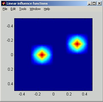
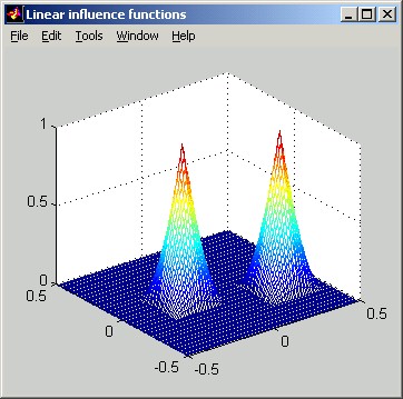
The following figures illustrate Linear influence functions. The horizontal distance scale of the slice plot is in meters. The vertical scale can be interpreted as relative: the poked actuator has been displaced by 1 unit.
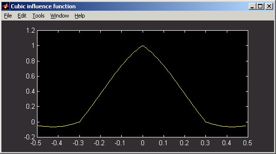
Cubic:
Cubic influence functions implement the form:
dx = (1-(Δx/wx)2)(1-(Δx/(2wx))) when Δx < wx ,
= ((Δx/wx)2 - (Δx/wx))(2 - (Δx/wx)) when wx < Δx < 2wx ,
= 0 when Δx > 2wx,
dy = (1-(Δy/wy)2)(1-(Δy/(2wy))) when Δy < wy,
= ((Δy/wy)2 - (Δy/wy))(2 - (Δy/wy)) when wy < Δy < 2wy ,
= 0 when Δy > 2wy ,
d = dx dy.
where
wx is the X half-width specified by the user in aogeom,
wy is the Y half-width specified by the user in aogeom,
Δx is the distance in x from the poked actuator, at the point where the surface deflection is to be determined,
Δ y is the distance in y from the poked actuator, at the point where the surface deflection is to be determined,
d is the surface deflection at the point located (Dx,Dy) from the poked actuator.
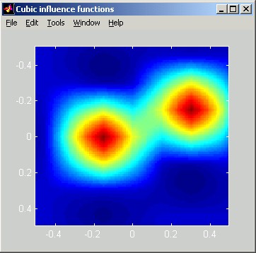
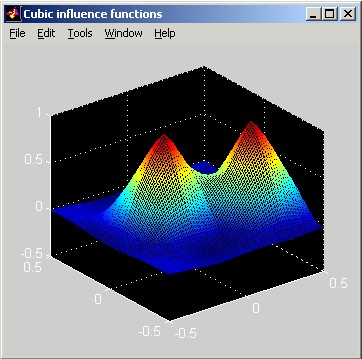
The following figures illustrate Cubic influence functions. The horizontal distance scale of the slice plot is in meters. The vertical scale can be interpreted as relative: the poked actuator has been displaced by 1 unit.
Review of Control Buttons:
![]()
While working in the AO Geometry Parameters window the main window diagram is not automatically updated. Instead the user must press the ![]() ,
, ![]() , or
, or ![]() buttons. The
buttons. The ![]() button causes all changes to window to be committed and closes the window.
button causes all changes to window to be committed and closes the window. ![]() commits the changes but leaves the window open and
commits the changes but leaves the window open and ![]() reloads the default configuration and leaves the window open.
reloads the default configuration and leaves the window open. ![]() closes the window while discarding the changes that were made since the last Apply.
closes the window while discarding the changes that were made since the last Apply.
Pictorial elements of the AO geometry diagram
This section summarizes the elements of the AO system geometry graphical display.
Axes: Indicate the coordinates and sizes of actuators, subapertures, and annular regions.
Red Circles: Subaperture inner and outer radii.
White Circles: Master actuator inner and outer radii.
Magenta Circles: Slave actuator inner and outer radii.
Green Circles: Inert actuator inner and outer radii.
Cyan Circle: The Green's function clamping radius when Green's function influence function is used. The clamping radius is often so large that it is outside the range of the displayed axes.
![]() Red Squares: Subaperture regions.
Red Squares: Subaperture regions.
![]() White Diamonds: Master actuators.
White Diamonds: Master actuators.
![]() Magenta Diamonds: Slave actuators.
Magenta Diamonds: Slave actuators.
![]() Green Diamonds: Inert actuators.
Green Diamonds: Inert actuators.
![]() Yellow Lines: Dependencies of slave actuators on particular master actuators.
Yellow Lines: Dependencies of slave actuators on particular master actuators.
Legend: Number of inert, slave, and master actuators, followed by the number of subapertures.